
 Ground-source heat pump
 Air-source heat pump
 Accessories
 What is a heat pump

 Air stoves
 Pellet boilers
 Ducted air stoves
 Hydro stoves
 Accessories
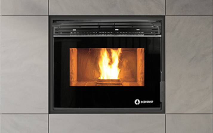 Insert pellet stoves
 Wood stoves
  Wood boilers
 Insert wood stoves
 Charcoal oven





When your Ecoforest pellet stove or hydro stove detects an anomaly in its operating parameters, it activates its electronic safety protocol and interrupts combustion. A warning message or an error code (from common alarms A001, A003, A004, or A099 to specific codes in the A000–A123 series) appears on the display or control panel.
In this official after-sales technical support guide, we explain the full meaning of Ecoforest’s error code table, the probable causes, and how to reset or unlock your pellet stove step by step.
📌 Quick summary: How do you reset or unlock an Ecoforest stove?
When an alarm message appears on the screen, the stove’s electronics immediately stop the fuel supply via the auger gearmotor and run the flue gas extractor at maximum power for a few minutes to cool the combustion chamber and clear residual gases.
Step-by-step manual reset:
- Allow the shutdown and cooling phase to finish: Do not unplug the stove during the safety shutdown cycle. Wait for the extractor to finish evacuating the smoke.
- Identify and resolve the cause of the error: Consult the detailed table below before switching the appliance back on. If you reset it without correcting the cause (for example, an ash-filled burner or an empty hopper), the alarm will immediately trigger again.
- Press the Off / Reset button: On the stove’s control panel or through the ecoSMART easynet remote management platform, press and hold the on/off button (
OFForON/OFF) for 3 to 5 seconds. The screen will clear the error code and enter standby mode (OFF or Standby). - Secondary power disconnection (if the panel is unresponsive): If the display does not respond after the fault has been resolved, switch off the i/o switch on the back of the stove, unplug the power cable, wait 30 seconds, and reconnect it.
⚠️ Important safety warning: Never try to ignite the stove again if the cast-iron burn pot is full of unburned pellets. Before restarting, open the glass door, remove any loose biomass, andclean the cast-iron burn potto ensure combustion air can flow freely.
📋 Complete table of Ecoforest error codes and alarms (A000 to A123)
Below is the complete list of warnings for the air stove range (such as Vigo III, Mónaco, and Córdoba Glass), ductable stoves (such as Bolonia and Dubai), hydro stoves (the Hidrocopper series), and pellet boilers (the Vap and Cantina series):
| Code | Alarm description | Main cause | Recommended solution |
|---|---|---|---|
| A000 | Disconnection with an active alarm | Power cable disconnected before clearing the existing error | DO NOT unplug the appliance to clear faults; use the keypad or control panel. |
| A001 | Low air intake vacuum | Insufficient draft due to dirt or loss of airtightness | 1. Clean the stove and burn pot. 2. Check that the door and ash drawer are not open. 3. Sweep the flue pipe. |
| A002 | High air intake vacuum | Excessive draft or unbalanced natural draft | Check the extractor settings and adjust excessive draft in the installation. |
| A003 | Minimum flue gas temperature | Flame extinguished or fuel supply depleted | 1. Check whether the hopper has run out of pellets. 2. Refill it with fuel and reset the alarm. |
| A004 | Maximum flue gas temperature | Combustion gases overheating | 1. The stove has exceeded its operating temperature limit. 2. Thoroughly clean the heat exchanger. 3. Reduce the power level. |
| A005 | Minimum NTC temperature | Water/NTC sensor reading below range | 1. Boiler installation incorrectly sized. 2. Appliance operating at low power levels. 3. NTC sensor disconnected or faulty. |
| A006 | Maximum or high NTC temperature | Overtemperature in the hydraulic circuit or convection system | 1. Bleed air from the heating circuit. 2. Improve dissipation of the generated heat. 3. Check whether the NTC sensor is short-circuited. |
| A007 | Minimum water pressure | Insufficient hydraulic pressure (< 0.8 bar) | 1. Refill the circuit to between 1.2 and 1.5 bar. 2. Check whether the water pressure switch is disconnected or faulty. |
| A008 | Maximum water pressure | Hydraulic overpressure (> 2.5 bar) | 1. Lower the operating pressure to 1.2 – 1.5 bar by bleeding the radiators. 2. Install a higher-capacity expansion vessel. 3. Bleed trapped air from the installation. |
| A009 | Minimum room temperature | Sensor detects values below the operating range | 1. Room temperature is excessively low. 2. Disable the room sensor or adjust the setpoints. 3. Lower the operating temperature. |
| A010 | Maximum room temperature | Sensor detects excessive room temperature | 1. Room is overheated. 2. Temporarily disable the room sensor. 3. Increase the selected operating temperature. |
| A011 | Minimum CPU temperature | Main electronic board below its temperature limit | Inspect the stove’s location and protect the electronics from extreme sub-zero temperatures. |
| A012 | Maximum CPU temperature | Central electronic board overheating | 1. Remove dirt accumulated at the rear of the appliance. 2. Check whether the air convection fan is dirty or faulty. 3. Correct the installation of the flue pipe. |
| A013 | Motor current below minimum | No electrical current draw from extractors or motors | Check the motors’ physical connections and wiring. |
| A014 | Motor current above maximum | Overload or mechanical blockage | Check for short circuits or physical jams in the motors (auger or extractor). |
| A015 | Very low air intake vacuum | Minimum draft level for safe operation not reached | 1. Carry out a full cleaning and maintenance service. 2. Seal the door, ash drawer, and cleaning access panel tightly. |
| A016 | Maximum flue gas temperature warning | Early warning of high temperature in the flue gas manifold | The system activates the safety protocol and automatically reduces the pellet feed rate to regulate itself. |
| A017 | Maximum NTC temperature warning | Warning of excessive heat in the convection or flow circuit | The controller reduces the fuel feed rate due to excessive temperature in the convection chamber or water flow circuit. |
| A018 | Extractor at 100% without sustained minimum vacuum | Flue gas extractor runs at maximum speed, but vacuum remains insufficient | 1. Soot has accumulated in the stove or boiler. 2. Carry out a full preventive maintenance service. |
| A019 | Flue gas extractor at 100% | Extractor saturated and operating at its power limit | Clean the flue gas passages and inspect the chimney flue. |
| A020 | Sensor error | Conflicting temperature sensor readings | Inspect the connections on the board; sensors may have been swapped. |
| A021 | Minimum outdoor sensor temperature | Outdoor temperature below -25 °C | Check the condition of the outdoor sensor or whether readings are outside its range. |
| A022 | Maximum outdoor sensor temperature | Outdoor temperature above 55 °C | Check that the outdoor sensor is not exposed to direct sunlight or faulty. |
| A023 | Minimum return sensor temperature | Abnormal reading in the water return pipe | 1. NTC sensor disconnected or damaged. 2. Inspect the peripheral module and check for an intermittent connection in the MODBUS cable. |
| A024 | Maximum return sensor temperature | Conflicting reading or overheating in the return circuit | 1. Return NTC swapped with the flow NTC. 2. Sensor short-circuited. 3. Check the hydraulic circuit and MODBUS cable. |
| A025 | Minimum sensor 1 temperature (DHW tank) | Low reading in the domestic hot water storage tank | 1. Installation or power output incorrectly sized. 2. NTC disconnected or incorrectly positioned in the sensor pocket. |
| A026 | Maximum sensor 1 temperature (DHW tank) | Excessive heat in the DHW tank | 1. Bleed trapped air from the circuit. 2. Correct inadequate heat dissipation or a short-circuited NTC. |
| A027 | Minimum sensor 2 temperature (DHW tank) | Low reading from the secondary DHW sensor | Check the position of the NTC sensor in its pocket and inspect the connections. |
| A028 | Maximum sensor 2 temperature (DHW tank) | Overtemperature at the secondary DHW sensor | Bleed the hydraulic circuit and check that the sensor is not short-circuited. |
| A029 | Minimum sensor 1 temperature (Buffer tank) | Low reading in the buffer tank | Check that the appliance is correctly sized and that the NTC sensor is properly seated in its pocket. |
| A030 | Maximum sensor 1 temperature (Buffer tank) | Excessive heat in the buffer tank | Check heat dissipation in the circuit and make sure air has been bled. |
| A031 | Minimum sensor 2 temperature (Buffer tank) | Low reading from the secondary buffer tank sensor | Check that the NTC sensor makes proper contact inside the tank’s sensor pocket. |
| A032 | Maximum sensor 2 temperature (Buffer tank) | Overtemperature at the secondary buffer tank sensor | Check heat dissipation, bleed air from the water circuit, and inspect the NTC sensor. |
| A033 | Burn pot open during the cleaning phase | The burner’s movable base does not close properly | 1. Check whether the burn pot base is blocked. 2. Clean the dirty sensor or check the motor and connector. |
| A034 | Burn pot open during the hardware test | Self-check detects the burn pot base is open | 1. Adjust or close the burn pot base. 2. Check the sensors, wiring, or loose connector. |
| A035 | Burn pot open during operation | Burn pot base disconnects or opens while running | Inspect for a possible blockage caused by clinker / slag or a limit switch fault. |
| A036 | Ash drawer open during hardware test | Sensor does not detect the ash drawer during self-check | 1. Empty the ash drawer if it is full. 2. Check the opening sensor and wiring. |
| A037 | Ash drawer open during operation | Ash drawer misaligned or full during combustion | 1. Check that the drawer is closed. 2. Carry out maintenance and check the microswitch. |
| A038 | Ash drawer open during shutdown | Opening detected during the shutdown cycle | Position the ash drawer correctly and check the sensor connection. |
| A039 | Burn pot cleaning failure | Failure after 3 attempts to open and close the burn pot | 1. Check that the doors and ash drawer cover are closed. 2. Remove mechanical blockages from the burn pot base. 3. Inspect the motor and wiring. |
| A040 / A045 | MODBUS RS485 communication failure | Signal interruption between the main CPU and peripheral module | 1. Check that the connection cable is firmly inserted. 2. If the cable is damaged, request a replacement from the Official Technical Service. |
| A041 | Zone 2 peripheral module | Communication error in the zone 2 module | Check the MODBUS wiring and power supply to the secondary board. |
| A042 | Zone 3 peripheral module | Communication error in the zone 3 module | Inspect the physical data connections to zone 3. |
| A051 | Pneumatic control silo out of pellets | No biomass in the pellet suction system | 1. Check the pellet supply in the external silo. 2. Check whether the pneumatic silo lid has been left open or the pipe is blocked. |
| A052 / A053 | Hopper silo 1 sensor detects no pellets | Hopper sensor does not detect fuel | 1. Refill the pellet hopper. 2. Clear the feed auger or recalibrate the sensor. |
| A054 | Silo control with 3 sensors | Fault in multi-zone silo detection | 1. Refill with pellets. 2. Identify which of the three sensors is faulty or dirty. |
| A055 | Burn pot cleaning | Informational status for the self-cleaning cycle | Normal process: the stove is performing its scheduled burner self-cleaning or waiting for a heating demand. |
| A099 | No pellets / Ignition failure | Flue gas temperature does not reach 80 °C | 1. Fill the hopper with quality pellets. 2. Check whether the auger gearmotor has stopped. 3. Check and manually reset the safety thermostat if it has tripped. |
| A101 to A103 | Maximum flow temperature (Zones 1 to 3) | Water overheating in the selected zone | 1. Bleed accumulated air from the circuit. 2. Increase heat dissipation or check the NTC sensor. |
| A104 to A106 | Minimum flow temperature (Zones 1 to 3) | Insufficient water temperature in the zone | 1. Installation incorrectly sized or excessive demand. 2. NTC sensor disconnected or damaged. |
| A107 to A109 | Maximum room temperature (Zones 1 to 3) | Room has reached a very high temperature | Temporarily disable the zone sensor or adjust the temperature setpoint. |
| A110 to A112 | Minimum room temperature (Zones 1 to 3) | Room temperature is below the low setpoint | Adjust comfort settings or check the zone sensor’s operation. |
| A120 | MODBUS communication failure (Zone 1) | Data loss between the CPU and zone 1 | Check the integrity of the RS485 network cable or request an inspection by the Official Technical Service. |
| A121 to A123 | THT1 / THT2 / THT3 not communicating | No communication with the zone’s THT thermostat | 1. Check the zone configuration in the menu. 2. Inspect the THT thermostat connection terminals. |
🔍 Step-by-step diagnosis of the most common codes
1. Error A099 / A003 / A001 (Ignition and air draft failure)
Warnings A099 and A003 indicate that the flue gas sensor has not exceeded the minimum temperature threshold for confirming a flame (usually 80 °C) within the time programmed for the ignition phase. Warning A001, meanwhile, is associated with insufficient air intake vacuum.
- Main causes:
- The holes in the perforated cast-iron burn pot are blocked by glassy deposits (clinker) produced by fuels with high ash content.
- The hopper is empty, or the biomass has absorbed moisture due to improper storage.
- The cartridge heater / glow plug is worn out and does not generate enough heat to ignite the pellets.
- Practical solution: Disconnect the stove and thoroughly clean the burn pot. Make sure the burn pot sits correctly in its housing so the forced airflow reaches the tip of the ignition heater.
2. Error A015 / A018 (Severe vacuum and flue gas evacuation failure)
Ecoforest electronics include a high-precision differential pressure sensor to verify that the combustion chamber maintains negative pressure (a safety vacuum) at all times.
- Main causes:
- The firebox door, ash drawer cover, or pellet hopper lid has not been closed tightly.
- The fiberglass rope seals are worn.
- Soot has accumulated in the flue gas manifold, on the heat exchanger’s internal baffles, or in the external chimney section.
- Practical solution: Check that the door fasteners are properly adjusted and clean ash from the rear access points. If the warning persists after clearing the flue gas outlet, contact the Official Technical Service to measure the vacuum with a manometer.
3. Manual-reset safety thermostat (Overtemperature systems)
If the stove body exceeds the safety temperature limit (90–95 °C) because of insufficient heat dissipation or continuous operation at maximum power without adequate ventilation, the electromechanical safety thermostat will trip.
- How to reset it:
- Switch off the stove, unplug it from the power supply, and wait for the metal body to cool completely.
- At the back of the appliance, locate the black plastic protective cap covering the reset thermostat.
- Unscrew the cap and firmly press the central button until you hear a mechanical “click”.
- Screw the protective cap back on, connect the power cable, and reset the appliance from the control panel.
🛠 Preventive maintenance to avoid alarm lockouts
The vast majority of error codes on Ecoforest pellet stoves and hydro stoves can be prevented by following a routine maintenance schedule:
- Clean the cast-iron burner: Vacuum ash from the burn pot before each ignition.
- Use ENplus A1-certified pellets: Certified biomass prevents slag from accumulating in the burn pot and helps prevent blockages in the feed auger.
- Clean the flue-cleaning chambers weekly: Remove fly ash accumulated behind the baffles and in the ash drawer.
- Arrange an annual technical inspection: Schedule a regular inspection with an authorized Ecoforest technician at the end of each heating season to check the seals, measure the vacuum level, and inspect the gearmotor’s mechanical components.
📞 When should you contact Ecoforest’s Official Technical Service?
If the error code reappears after you have followed the troubleshooting steps and reset the control panel (especially for MODBUS communication failures A040/A045, motor errors A013/A014, or inconsistent NTC sensor readings A020/A023), do not attempt to work on the electronic mainboard or dismantle internal mechanical components. Complete the contact form.
